
Mini LED backlight structural joints
Review non-optical structural fixation, dispensing locations and effects on the light path.
Displays & optical modules
Start with structural and perimeter joints, then review the assembly process.
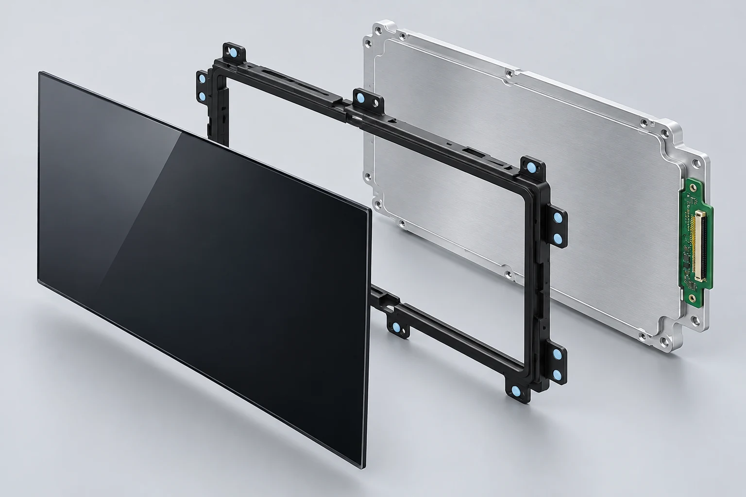
Review non-optical structural fixation, dispensing locations and effects on the light path.
Review frame fixation and perimeter seals; confirm optical-bonding scope separately.
Review supports, housing joints and service conditions.
Share the substrates, optical area, joint gap and cure process.
These links open existing material categories. Review suitability for the location against substrates, process and evaluation conditions.
Review dose, light-path clearance and cure access at the actual non-optical structural joint.
Separate frame/perimeter joints from optical lamination; compare substrates and processes.
Review positioning, joint geometry, optical-surface contamination and servicing.
Optical lamination requires review of the light-transmitting layer, bubbles and display effects. A perimeter-fixing category alone does not establish suitability for full-area optical bonding.
Structural fixation differs from die attachment, underfill and electrical interconnection. A module-assembly category does not establish suitability for chip-level packaging.
Open a component to see the bonding location and evaluation inputs.
Where the design uses bonded frames, supports or backplates, locate the structural joints from the drawing. Keep material away from optical films and emitting areas.
Locate frame fixation and perimeter seals around the display module, and establish whether the joint touches the optical area.
Review supports for lenses, filters and prisms, along with display housing joints. Distinguish locating surfaces from surfaces carrying light.